Login / Register
Ethernet bunch of flash in an NVMe-oF™ network for low-cost storage at scale
NVMe over Fabrics (aka NVMe-oFTM) is an emerging technology that enables disaggregation of compute and storage in the data center. Micron is helping to unlock the benefits of NVMe-oF by collaborating with key technology partners such as Marvell, Foxconn-Ingrasys and NVIDIA. We are also innovating new technologies such as heterogenous-memory storage engine (HSE) that will help optimize access to flash storage at scale using NVMe-oF.
What is NVMe-oF?
NVMe-oF literally extends the NVMe protocol over a network, increasing the reach well beyond the server chassis that confines SSDs today. While NVMe has been around since 2011, the fabrics extension was first standardized in 2016. Because NVMe-oF leverages NVMe, it inherits all the benefits: a lightweight and efficient command set, multicore awareness and protocol parallelism. NVMe-oF is truly network agnostic as it supports all common fabrics, including Fibre Channel, InfiniBand and Ethernet. Figure 1 compares NVMe and NVMe-oF models and highlights the various network and network transport options that are available to the user.
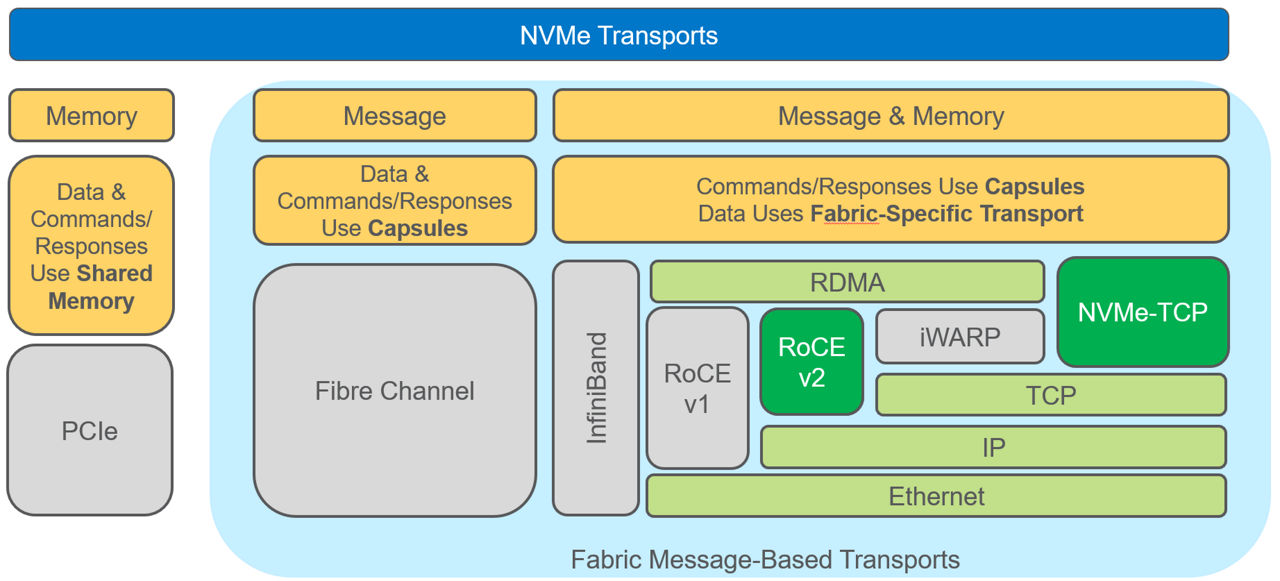 Figure 1: NVMe and NVMe-oF model comparison
There are two relevant Ethernet transport options, RoCE v2 and NVMe-TCP. Each has its advantages and disadvantages. RoCE v2 is lower latency but requires specialized RDMA-enabled NICs (RNIC), while NVMe-TCP transport has higher latency and higher CPU use but does not require any specialized RNICs. Instead, it makes use of a standard NIC. RoCE v2 is more prevalent in the market right now.
What are the benefits of NVMe over Fabrics?
With just NVMe, you are essentially restricted to the server chassis or the rack using PCIe switches as a means of scaling. While this is a perfectly valid way of scaling storage, it is arguably limited in scope and reach. NVMe-oF allows a virtually unlimited amount of storage to be connected across a data centerwide radius.
Today, NVMe-oF is well established, with many users embracing the technology to connect all-flash arrays (AFAs) to servers. However, the full benefit of NVMe-oF will only be realized when compute and storage are fully disaggregated. That is, a pool of NVMe SSDs is made available over the network to a pool of servers in a way that allows one to provision both compute and storage on demand. Disaggregation increases scalability and shareability of storage and enables composability, as shown in Figure 2.
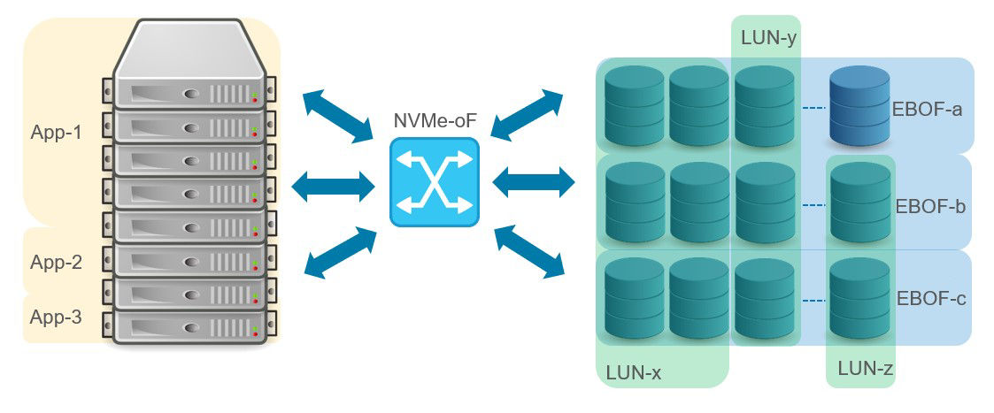 Figure 2: Disaggregation of compute and storage
Another dimension to disaggregated storage is storage services (that is, data protection, replication, compression, and others). Storage services can be managed by the servers (onload model) or offloaded to data processing units (DPUs) that are close to the actual storage. Tradeoffs must be made. The onload model consumes additional CPU cycles and network bandwidth but minimizes cost, while the offload model increases cost and, depending on provisioning, can create bottlenecks. The pursuit of low-cost storage at scale leads to an onload attached storage strategy due to the TCO (total cost of ownership) advantages.
What are EBOFs, JBOFs and JBODs?
There are two ways to connect a “bunch of flash” into a NVMe-oF network: using an Ethernet Bunch of Flash (EBOF) or using a Just a Bunch of Flash (JBOF). Don’t confuse a JBOF with a JBOD (Just a Bunch of Disks). A JBOD is typically used to scale storage in a rack using NVMe over PCIe. An EBOF or JBOF can be used to scale storage across a data center using NVMe-oF. As seen in Figure 3, a JBOF uses a PCIe switch to fan out to the SSDs, while the EBOF uses an Ethernet switch to fan out to the SSDs. Both a JBOF and an EBOF connect back to the servers using NVMe-oF.
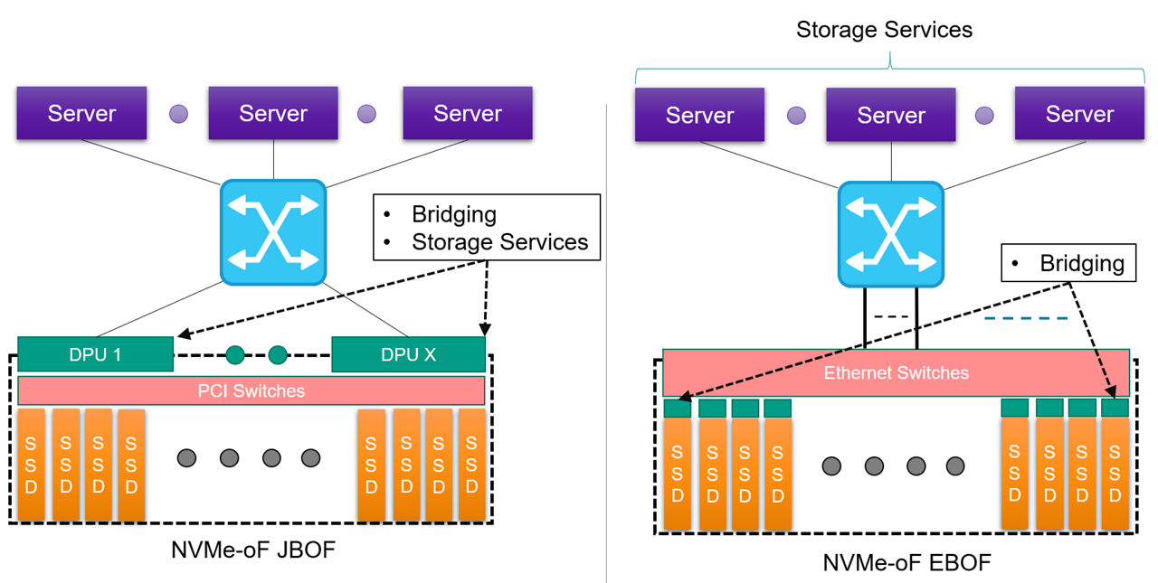 Figure 3: NVMe-of network comparing EBOF and JBOF
The main difference between the two approaches, beyond the obvious Ethernet vs. PCIe switching, is where the NVMe to NVMe-oF conversion takes place. On the JBOF, the conversion or bridging is at the periphery of the shelf using one or more DPUs (x DPUs to y SSDs, x:y ratio). On the EBOF, the bridging is done within the SSD carrier or enclosure (x bridges to x SSDs, 1:1 ratio). While the JBOF has an advantage of using the processing capabilities of the DPU for running storage services, it does present a potential bottleneck and comes at additional cost and power over the EBOF model. The cost tradeoff and bottlenecking come into play when the ratio of bridges to SSDs is not 1:1.
We’re testing our system with the Marvell 88SN2400 and Foxconn-Ingrasys EBOF
Through a collaboration with Marvell and Foxconn-Ingrasys, we’ve been testing our Micron 7300 mainstream NVMe SSDs in NVMe-oF environments under a variety of different applications and workloads.
Before looking at this testing, let’s look at the Foxconn-Ingrasys EBOF and Marvell’s 88SN2400 converter controller and Prestera® CX 8500 switch.
Marvell’s 88SN2400 is an NVMe-oF SSD converter controller for cloud and enterprise data centers. This, in combination with the Marvell switch, essentially allows you to convert or “bridge” between NVMe and NVMe-oF. The 88SN2400 converter controller is a critical component to the Foxconn-Ingrasys EBOF and, together with our Micron 7300 SSDs, makes for an impressive high-performance 2U shelf of storage (up to 73.1 GB/s of bandwidth and up to 20 million IOPs). Figure 4 shows the Foxconn-Ingrasys EBOF, with 24 U.2 slots in a 2U enclosure.
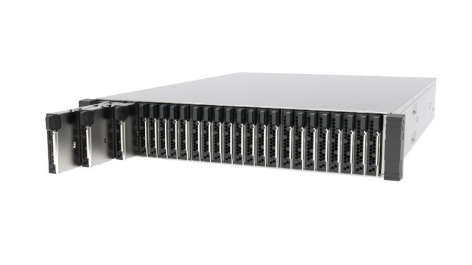 Figure 4: Foxconn-Ingrasys EBOF
Figure 5 displays the Foxconn-Ingrasys SSD carrier with the Marvell 88SN2400 converter controller.
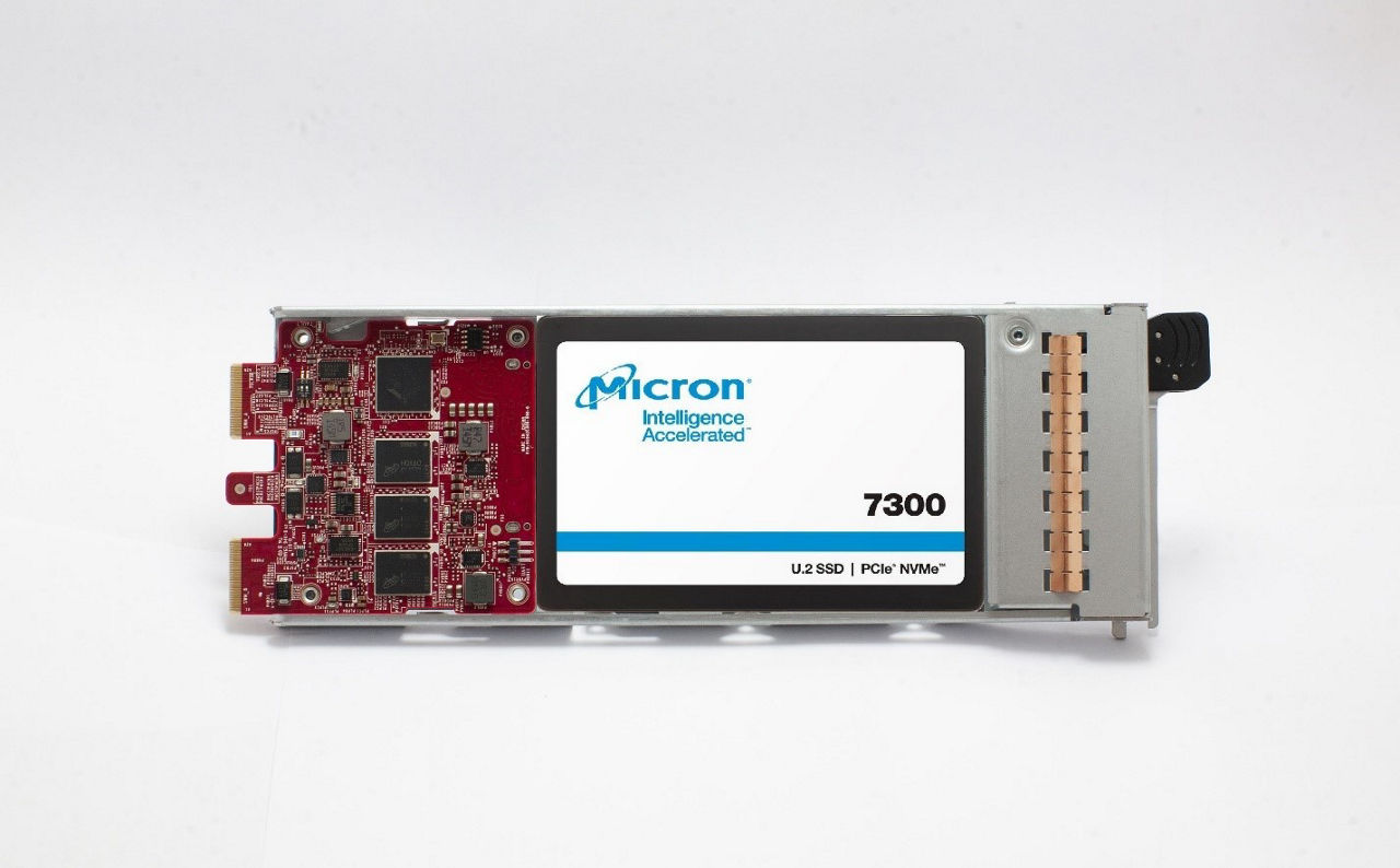 Figure 5: Foxconn-Ingrasys U.2 carrier with 88SN2400 converter controller
The Foxconn-Ingrasys U.2 carrier takes a standard U.2 SSD form factor. The U.2 carrier supports dual Ethernet ports to address applications that need path redundancy, and it has a single PCIe Gen3 x4 on the drive side for the NVMe SSD.
Marvell’s 88SN2400 converter controller supports both RoCE v2 and NVMe-TCP transports. However, for our testing, we’ve focused on RoCE v2.
How do things scale with NVIDIA™ GPUDirect™ Storage (GDS)?
We’ve been doing a lot of work with our SSDs in artificial intelligence and machine learning workloads using NVIDIA™ GPUDirect™ Storage (GDS). We wanted to see how things scaled in a fabric environment by connecting a Foxconn-Ingrasys EBOF with Marvell’s 88SN2400 converter controller to a NVIDIA DGX™ A100 system. This is a simple gdsio (GPUDirect Storage I/O) tool test comparing bandwidth and latency both with and without GDS in an NVMe-oF environment.
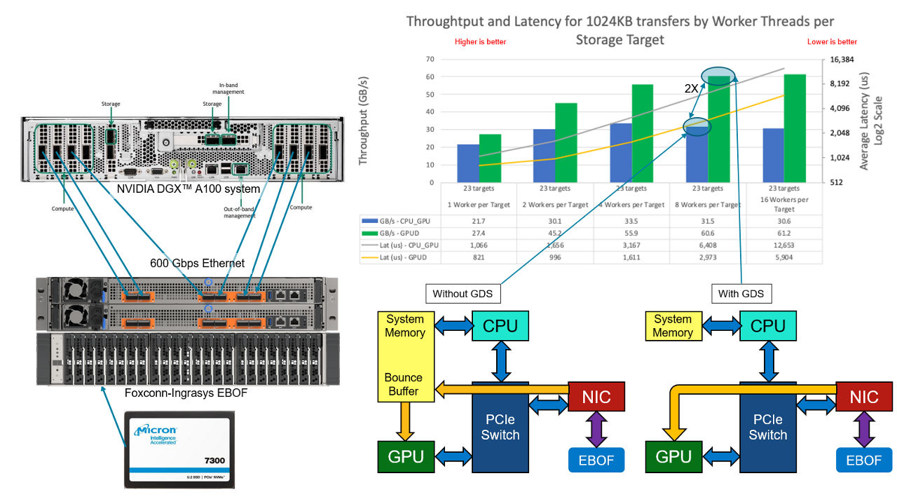 Figure 6: DGX™ A100 with EBOF
In Figure 6, we have an EBOF loaded with Micron 7300 SSDs connected directly to an NVIDIA DGX™ A100 using six of the eight compute network ports, giving 600 Gb/s of available network bandwidth. GDS enables data to be transferred directly between peers, skipping the high-latency bounce buffer that is used when GDS is not enabled. In this test, we are extracting the full capabilities of the SSDs in aggregate (~61 GB/s) for the workload. Future testing will add an Ethernet switch and scale up the number of EBOFs even more.
You can learn more about this testing at FMS 2020 in the AI track via a presentation by Wes Vaske, principle storage solutions engineer, entitled “Analyzing the Effects of Storage on AI Workloads.”
How can NVMe-oF create scale with an HSE?
Here at Micron, we’ve been working on some amazing technologies, one of them being the heterogeneous-memory storage engine (HSE). HSE is a flash-aware storage engine that enhances the performance of storage-class memory (SCM) and SSDs. It also increases the effective SSD life span through reduced write amplification, all while being deployed at a massive scale. NVMe-oF is an ideal way to further create scale with HSE. To validate the effectiveness of HSE in the context of fabric attached storage, we’ve done some testing using MongoDB with YCSB (Yahoo! Cloud Serving Benchmark). In Figure 7, we compare performance between the default built-in MongoDB storage engine (WiredTiger) using local Micron 7300 SSDs and Micron’s HSE using Micron 7300 SSDs in an EBOF.
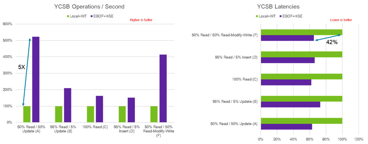 Figure 7: WiredTiger compared to HSE
The effectiveness of HSE in a fabric environment is quite dramatic when compared to the legacy WiredTiger storage engine used in MongoDB with a local SSD. We can achieve up to five times the improvement in YCSB operations per second and a 42% reduction in latency while simultaneously increasing the scalability of storage.
You can learn more about this testing at FMS 2020 in a presentation made by Sujit Somandepalli, principal storage solutions engineer, entitled “Extend Your Storage With NVMe Over Fabrics.”
What is the future of NVMe-oF?
NVMe-oF is an enabling technology that will eventually lead to fully disaggregated data centers where applications can be composed and then dynamically provisioned with the appropriate amount of compute and storage in a cost-effective manner.
Today, low-cost bridges or DPU-based platforms are used to connect and bridge NVMe SSDs into an EBOF or JBOF. In the future, we may see native NVMe-oF SSDs further decreasing TCO and improving performance.
Micron is designing next-generation data center SSDs with capabilities and features that are optimized for NVMe-oF applications.